Mechanical CADM, Where Does It Go From Here?
Throughout my work in the field of CADM (Computer-Aided Design and Manufacturing), especially precision machining, the following question arises: "Where does CADM go?" What has yet to be achieved? How can the precision machining be further streamlined, while reducing costs? Have we not reached the limit in developing technological tools in this field?
In this article I will try to answer these questions and many more, as well as raise thoughts and ideas regarding the next CADM generation.
The history of mechanical CADM is fairly young compared to the ancient history of metalwork, which was essential to human development. Early humans used rocks and other basic tools and techniques for metal processing, creating tools and utensils for everyday use.
The need for precision machining came early last century, in parallel to the development of the automotive and aviation industries. The need to create a relationship between moving parts required the utmost precise manufacturing, in order for the planning concept to become a tangible operative product.
The initial design previously involved a pen, a paper and some mathematical formulas for strength calculating; however, since the need to create more complex, resilient, smart - and above all - reliable and safe “machines”, the pen & paper idea was abandoned for the sake of the new computer generation. Without going deeper into the details, I will only say that admittedly, today, we are all largely dependent on the computer in nearly all everyday’s aspects.
We are striving to improve our level of precision, from a-thousandth- to millionth-of-a-millimeter order; and yet, the plant quality auditor would sometime indicate an incompetent component, and order to repeat the entire process.
Today, with the advancement of planning software, the greater is the need for a program with stronger manufacturing and more advanced technological capabilities; this is crucial in order to enable the ambitious planning engineer to simulate his idea as a final product. Well, precision machining manufacturing is often very difficult, and sometimes impossible.
At this point we are assisted by the precision machining and cutting tool manufacturers. The development in this field is tremendous, and several separate articles be dedicated only to that. In my opinion, the development in precision machining capability is the catalyst in the mechanical CADM development.
"Cimatron", an Israeli 25-year old company, championed the need to be at the forefront of technology, with the advancing capabilities of precision machining and cutting tools.
The ultimate desire of every precision machining plant owner is – to have the component prepared and ready not later than five minutes after receiving “green light” to begin manufacturing, including the long process of programming, NC, manufacturing, chemical processes and final review.
There is yet much to do to improve the gap between the ideal and reality. Cimatron is making great effort to fill that gap, using the ability to shorten the NC programming time (the time duration from receiving the manufacture OK to begin the manufacture) and the machine’s processing time.
High Speed Cutting
Today's most advanced CNC machines technology is the HSC (High Speed Cutting). The machine's ability to run at high speed, while maintaining a uniform speed, without stops or slowdowns - with proper cooling of the tool, while spreading the chips and a "smart" computer who can read a large number of Gcode rows rapidly and while looking forward to maintain continuity of the program and toolpath, in a proper cutting speed based on the manufacturer’s instructions, in order to get a high quality surface.
"Cimatron" milling software includes several methods to utilize the machine’s HSC capability:
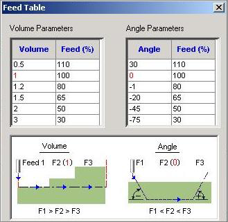
Intelligent use of the optimizer – for a continuously uniform load. How? At each processing stage, the software knows the quantity of raw material left by the end of the last operation, and the quantity of raw material on the tool, in the tool-operator interface. The operator sets the desired processing data (as defined by the manufacturer) which serves as a marker between chip volume and progression speed. Accordingly, the software will calculate at anytime the new processing speed, depending on the amount of raw material removed by the tool, i.e. if the tool is overloaded (100% of the tool’s diameter), the software will decrease the speed of progress; if the tool is partially loaded, the software will increase the speed of progress. This option enables the machine operator to optimally use their capabilities, resulting in significantly reduced processing times.
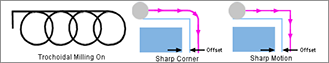
A second option: without changing the progression of the machine, when the software detects a large chip load on the tool, it changes the toolpath to a trochoidal toolpath, that is - a linear progression through spiral toolpath on an XY-plane and thereby allows the operator to maintain maximum progression without being concerned about breaking the tool due to overload. The possibility of high-speed operation, as well as small chip load on the tool, extends tool’s lifespan, increases machine utilization and reduces processing times.
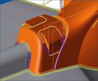
Another option, and perhaps the most important of all, is the elimination of sharp toolpath when changing machining directions. For example, changing from moving along X-axis to moving along Y-axis requires the machine to decelerate along X-axis, perform a momentary stop at the rotation axis, and re-accelerate to a progression speed along Y-axis. It turns out that acceleration and deceleration are one of the significant factors in increasing component processing times. Cimatron, by eliminating the sharp toolpath and carrying out corner rounding, taking into consideration the change in angle, enables the machine to work at uniform speed in a tool-operator ratio, thus saves processing time and achieves better surface quality than that achieved by usual processing.
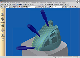
Five-Axis Machining
Another technology that has recently been more and more incorporated into “small” (3-6 CNC machines) precision machining plants, is a 5-axis computerized machine centers. The reduced costs of these machines (in comparison with previous years) and the strong CADM capabilities allowing fast and precise 5-axis programming have definitely contributed to this welcome change.
This technology allows for completing the machining in almost a single mounting, and when the component is unmounted, only one side remains for further processing.
This allows reducing processing time, as well as increasing precision and relativity between the various processing phases on the processing surfaces.
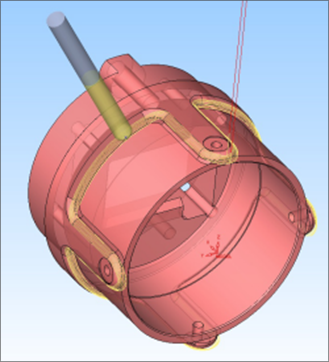
Cimatron software package enables the capability of continuous (simultaneous) 5-axis operation, taking into consideration the operator’s position on the table (it is possible to place the operator off the center of rotation-axis, and the software can automatically calculate the precise location without the need to define a homefor each angle processing); and taking into consideration length of the tool in respect to the axis and the gripper (the software can assure placing the machine’s head or table, to keep a safe distance between them and the operator).
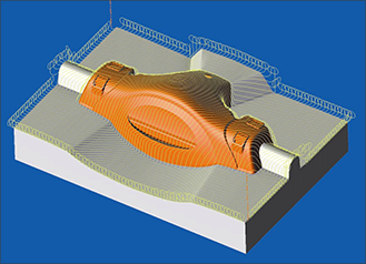
Operating a five-axis machine allows "stitching" surfaces with high accuracy, better surface quality and processing time shorter than that of the three-axis machines. The ability to continuously tilt the operator in a desired angle provides two processing options:
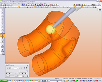
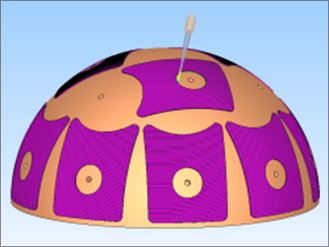
Working on a surface with a flat tool and lateral strides that are relatively large for working with a spherical tool. Cimatron ensures maximum perpendicularity between the bottom of the tool and the operator. This work is especially appropriate for curved surfaces.
Working on a spherical tool that requires small lateral steps, that is, a large number of toolpaths in order to obtain the desired surface. Cimatron assures working with the tool tangentially, avoiding working with the “forehead”. Why so? Because the cutting speed at the center of the tool is zero, so working with the bottom of the surface tool would result in poor spherical quality. Therefore, it is highly important to work tangentially with the spherical tool. This capability is only possible with five-axis machines and simultaneous work.
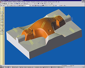
Processing of Material Residues
The advancement of three-axis machine centers technology is directly influenced by the rapid development of CADM software. In the past, in order to process three-dimensional surface, the operator would need a manual computer; by finding the appropriate formula and writing it the Gcode language, toolpaths could be calculated. Although the code was fairly short, it was necessary to spend valuable time, as well as being assisted by a skillful programmer, in order to obtain the appropriate formula. Any change in the surface required formulating new mathematical calculations.
Today, when the surfaces are obtained as a mathematical model, directly from the designer, the CNC programmer is not required to know calculus. S/he would just use the CADM to perform the calculation work. Thus, calculation time is saved, while increasing the product’s immediate changeability. There is a low importance to the length of the code, since the machine controller is capable of receiving a code of virtually unlimited length.
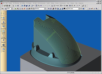
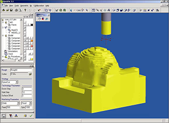
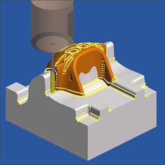
Cimatron has the option to process the component in various stages with other processing tools, while taking into consideration the material residues. For example, the first tool (20 mm crusher) is used to perform the initial material removal work - rough machining in large steps, with a 0.2-mm-offset of the final size. This tool is certainly not capable of reaching all corners, thus leaving rough steps; for that reason, we use a second tool (10 mm crusher) and continue with the removal of rough material, in small steps, with the same offset (0.2-mm-offset of the final size).
Since Cimatron knows, at each stage of the work, the amount of removed material and the amount of raw material to be removed, it will create work toolpaths for the second tool only in areas where there is raw material to be removed – thus preventing unnecessary toolpaths. As a result of this preliminary processing, the finishing tool is left with a uniform 0.2-mm-offset of the final size, so the forces applied on it are uniform and the tool’s lifespan is longer.
The program allows working with several tools (usually spherical or flat with corner radius), with the same technology, so the operator selects the sequence of tools s/he wants to use (in descending order) Cimatron calculates optimally the toolpaths, with full consideration of the quantity of raw material left by the previous tool, as well as the current tool's ability to remove it.
This powerful capability of Cimatron allows the operator maximum flexibility in manufacturing or applying necessary changes while programming. For example - the component might be modified by the designer; there is no suitable tool in the plant; there is a need to manufacture similar components in different sizes; etc.
So far, I have reviewed some of the recent developments in the field of mechanical CADM, but - have we reached the limits of development in this field? Unfortunately, any answer to this question might be too vague to discuss, since changes in tools and CNC machines are revolutionary at any given period.
In conclusion, I will my vision for the next generation of mechanical CADM:
After the product is planned and designed, a mathematical (solid) model is delivered to the Manufacture Department. The "next generation" CADM software model slices the model in micron-thick horizontal sections. According to this slicing, the "Super Printer" constructs the component bottom-to-top, layer upon layer (similar to the Stereo Lithography system, building a three-dimensional model from a polymeric material).
This new technology helps us manufacturing each part in any form. Here are some of the advantages of this “printing”:
The transition from a mode to beginning of manufacture will be a matter of minutes. The components will be manufactured using every material required, including various hard and/or unprocessable; the manufacture speed will be similar to that of a plastic injection pattern (a few seconds per portion), manufacture of multiple part per portion; high surface quality; material properties are left unchanged or even improved (hardness, strength, fiber orientation, etc.); desired exterior siding; and above all – uniform accuracy of all components.
Well, is the "next generation" CADM imaginary? Wait a decade or two and see for yourself.