MTM Machines – The Top of Technological Progress
The dream of every precision machining factory owner is to own a machine which is actually a “factory”, a machine that meets most of the technological requirements and produces the most complex parts in minimal time. Well, this dream could come true through a single manufacturing machine, machine centers and an engraving machine integrated: Multi-Tasking Machine: two axes, a number of turrets, raw material processed in multiple stations; the employee moves from one axis to another, without human intervention, where on one side raw material enters and on the other side a complete part goes out. They are faster, more accurate and more sophisticated. These machines confirm the concept of "technological streamlining while increasing manufacturing power."
As opposed to machine centers with five (5) and six (6) axes, basic MTM machines contains ten (10) axes and more.
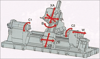
To understand what ten-axis means, let’s take a look at Figure 1: the axes are defined according to the nature of the movement which they are able to make:
Primary axis - C1 - rotary, secondary axis (rear) C2 – rotary – also capable of moving along the axis, W (Z-axis of the machine).
Top turret designed for engraving and milling – a rotary axis, sidelong on B-axis and moves vertically on XA-axis which moves horizontally on both ZA- and Y-axes.
The lower turret moves on two axes - ZB and XB - and can sometimes be added with milling tools.
The combination of axes (Figure 2) is virtually infinite and there are countless options for a scheduled work. Here are some common combinations:
Top Turret (A) mills or engraves on the primary axis (C1), while the lower turret (B) works on the secondary axis (C2) and vice versa.
The two turrets engrave or drill simultaneously on the same primary or secondary axis.
Top turret performs five-axis machine centers simultaneously on the mounted part of the main axis, while the lower turret performs engraving on the secondary axis and vice versa.
The concept of "the sky is the limit" accurately describes the various timing options of these machines.
The concept of MTM contains a wide range of milling-integrated engraving machines. Each MTM machine manufacturer regularly develops and renovates a unique configuration that improves the manufacturing process and increases the machine’s capabilities.
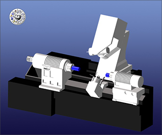
The structure of the two axes is almost constant, but their location varies. Normally, they face each other and the component is delivered by a synchronized movement of the secondary axis toward the primary axis, but oftentimes they are one above the other, where the component is delivered from one to another with the help of a robotic arm or a synchronized component-gripper. Most of the axes are horizontal but some can be manipulated with computer-controlled angular siding.
Common changes in configurations between different machines are: number of turrets, movement abilities and inabilities of each turret, tool-fed turret by an external tool replacing machine (there are tool replacing machines that contains hundreds of tools) or rotary turret when the tools are fixed on it, a turret with milling and/or engraving stations. In fact, the structure varies depending on the fertile brain of the machine planner, and indeed, as I wrote earlier, "The sky is the limit".
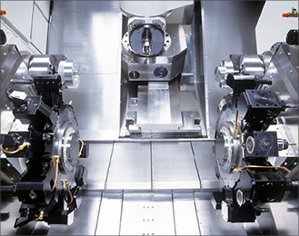
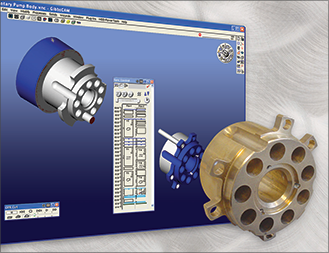
For example in Figure 3 we can see shows a two-axis MTM machine, an upper turret capable of replacing milling and engraving using an external tool replacing machine, and two turrets with 12 tool stations each, and full milling and engraving capabilities.
There are a number of reasons why the use of MTM machines is mandatory; here are some of the most important ones:
The first reason stems from the strict requirements of the planners and customers. Higher accurate manufacture requires no mounting change during the process, since each additional mounting causes a certain loss of accuracy, which may lead to disqualification of the component. Therefore, with a machine combining engraving and five-axis machine centers, plus – the component can be transferred from one side to the other at the same processing without the operator’s intervention (which may lead to some loss in accuracy); the process can be done at once, meeting the stringent accuracy requirements.
The second reason is the number of components required for manufacturing: a larger amount of work requires more automation of the process. In an MTM machine, after programming and orientating tools and machine, manufacturing continues automatically without the need for an operator. Certainly, these machines can be added with a rod feeder directly into the axis, or be fed with raw materials by a robot - and the same applies for the unloading the finished component. These machines work independently 24/7 including weekends and holidays; they never ask for leave, severance pay, holiday pay, etc. - an ideal employee.
A third reason: the relatively small floor space required by an MTM machine. Today, when there is a lack of manufacturing areas and the cost per square meter is literally skyrocketing, there is a high importance area to the minimal area it occupies, while “replacing" several individual milling and/or engraving machines, without detracting the amount of components processed at the same time.
Another reason, which is not technical, but no less important, is the cost of the client. In a competitive market such as ours, the price is a most important factor in manufacturing a component. An MTM machine - an "independent plant" - is capable of manufacturing an accomplished component significantly faster than manufacturing the same component using a number of different machines. Thus, a precision machining manufacturer is capable of dealing better with customer’s requirements and competitors.
However, MTM technology is still overshadowed by the question of operation; as the machine is more complicated, so there is a higher demand and a greater need for CAD software to provide a complete solution to the entire technological process. The software has to behave as it is an MTM machine - considering the precise structure of the machine, supporting unique processing tools and timing capabilities between the various processing stages in the manufacturing process. Cimatron GibbsCAM has been designed and developed specifically for providing the perfect solution to support these machines: operating simplicity on the one hand, and technological strength together with amazing results on the other.
When getting started with GibbsCAM software, the user defines the type of the machine which will be used for processing (Figure 4). Depending on the machine selected, all relevant options for that machine become available. If the user has defined a Mazak Integrex machine, with two axes and two turrets – relevant options will immediately become available, such as: transferring part of the primary axis to the secondary axis, using five-axis, and other machine centers (milling) and engraving capabilities of the machine.
Throughout the entire process of defining the processing for milling and/or engraving, there is a processing managing and scheduling (Figure 5). This unique function allows the user to set up simultaneous processing performed by the turrets, in order to reduce processing time, for example - engraving on the primary axis with two turrets simultaneously (one from above and one from below) to achieve a faster removal. The software is able to synchronize the start times of processing each chip during the engraving process, and assures that each turret processes uniformly, taking into consideration the other turret.
The software can synchronize integrated counter-drilling operations of the upper turret against the lower turret, which allows time-saving. This capability also enables supporting the operator against bending. In addition, if there is a lower turret milling capacity, it is possible, similarly to the counter-drilling, to perform heavy milling operations on both sides of the operator, without concerning about one-side pressure on him/her.
When creating the scheduling between various processing works, you may diagnose the long processing, which are the "weakest link" during manufacturing and place other processing works to operate in parallel on the timeline, changing the technological process and consequently save valuable manufacturing time. The ideal solution is performing continuous work on both axes to avoid "idle time for one of them, thus leading to reduced manufacturing time.
This scheduling capability between the turret and axes for integrated workflow requires using the software’s module to prevent collisions, as well as simulating the process entirely (Figure 6). Initially, when we defined the type of machine with which we would process the component, a structure in a “solid” format is loaded, for the purpose of simulation. The machine is modeled" inthe software uniquely, and the movement capabilities and limitations of each axis is defined (in size and degree), plane of motion and contact limitations. As the user correctly and accurately sets the tool offset, lengths, types and locations of the grippers – which reduce the number of errors to zero.
In order to get a machine simulation as real as possible, we should receive from the manufacturer/importer the machine structure known as a Solid file; this allows the GibbsCAM user or the Cimatron application engineers to specifically define the machine for the customer according to the exact measurements obtained from the file. Notice that machine manufacturers are not willing to deliver the "Solid" file of the machine structure, to avoid exposing the machine structural secrets, and rightly so, but you can still get only the axis structure and their real location in relation to another. Entering more accurate data to the GibbsCAM, will lead to better software/machine matching.
In view of the experience and the wide use of Cimatron GibbsCAM, it is possible that the software generates a Gcode for MTM machines, which includes full scheduling between the various processing works; thereby, an operator does not need to perform any manual editing of the program.